Learning Objectives Define the following: Dimension line
Learning Objectives The American National Standards Institute (ANSI) and the American Society of Mechanical Engineers (ASME) work hand in hand to set the standards in technical drawing. 2
Learning Objectives Define the following: Dimension line, Extension line, Reference dimension, and Leader Be able to understand the basic rules of dimensioning.
Be able to understand the basic rules of dimensioning. Apply dimensions to objects in accordance with engineering standards. 2.
The American National Standards Institute (ANSI) and the American Society of Mechanical Engineers (ASME) work hand in hand to set the standards in technical drawing. 2.
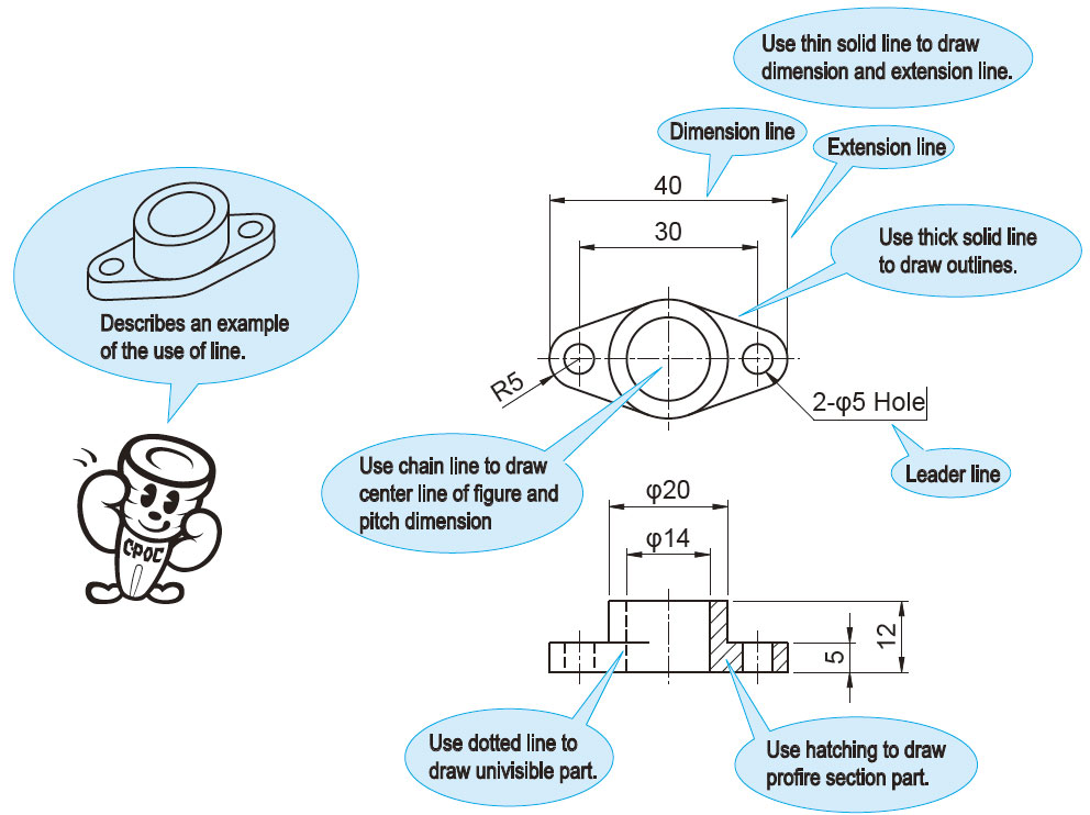
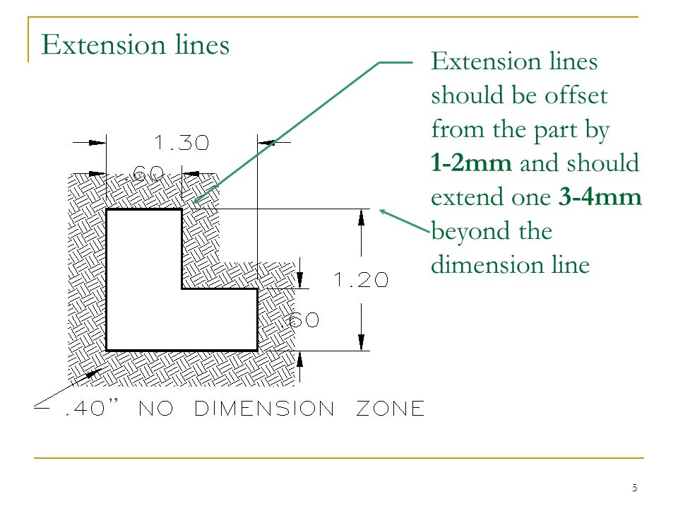
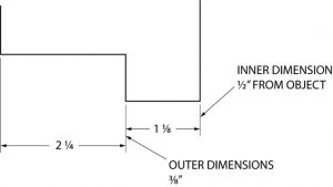
They show the exact distance of the dimension. They are drawn right angle with the dimension line. They do not cross arrowheads.
Extension lines Extension lines should be offset from the part by 1-2mm and should extend one 3-4mm beyond the dimension line.
It indicates the direction and extent of a dimension.
Any dimensions beyond it must be a minimum of 6mm.
Arrowheads: Should be 3 times longer than the wide.
Avoid dimensioning to hidden features. Always place the dimension where the characteristic shape is shown in the most descriptive view. Always dimension holes in their circular view by stating the diameter of drilled holes. Specify the hole depth of special features such as countersinking with a note following the dimension. Dimension rounded corners and arc features as radii where they appear in their rounded views. If the same value is repeated many times, then use a general note for the features. Always place the first row of dimensions a minimum distance of 10mm away from the edge of the part. Additional stacks can be a minimum 6mm away from each other. Keep dimensions between the views whenever possible. Extension lines may cross each other and over other lines on the part, but dimension lines should never be crossed. The overall dimension should always be given. It should be placed outside of smaller dimensions and be the furtherest dimension from the part. 16.
When all of the dimensions are expressed in inches, do not use inch mark ( ) or the abbreviation for inches (in.) For drawings dimensioned in inches, values less that one inch should not be preceded with a zero. For metric drawings, omit the use of the millimeter (mm) notation following the numeral, as millimeters are the default units. Conserve space and time by using abbreviations and standardized symbols whenever possible. Reference dimensions should be placed in parentheses or should include the abbreviation REF . Basic sizes (to be toleranced) should be placed inside a rectangular box. Extend leaders from the first of last word in a note. Point them toward the center of circular features that they are specifying. Place dimensions among the various views to avoid crowding. Stagger horizontal dimensions to avoid contact or crowding of values. 16.
See Essentials of Engineering Design Graphics Chapter 4.
There is one exception:…… When the hidden line is a finished (√) surface. See Essentials of Engineering Design Graphics Chapter 4.
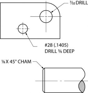
4. Always dimension holes in their circular view with the Ø. Specify special features (hole types) with a note. Also: Remember to locate hole position with ordinate dimensions to hole centers. See Essentials of Engineering Design Graphics Chapter 4.
(ALL FILLETS AND ROUNDS ARE .125R).
Additional stacks of dimensions can be a minimum of 6mm away from each other.
9. Keep dimensions between views whenever possible .
Extension lines may cross each other and over other lines on the part, but dimension lines should never be crossed. (Hint no arrow-headed lines can cross arrow-headed lines).
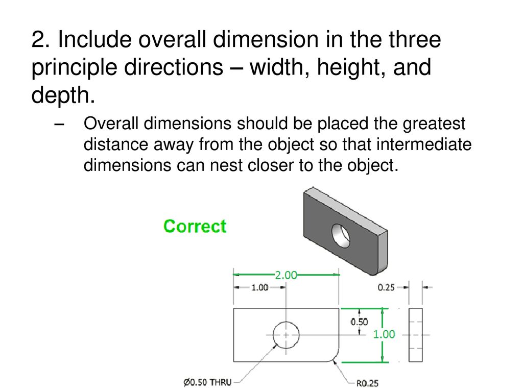
11. The overall dimension should always be given. It should be placed outside of smaller dimensions and be the farthest from the part.
12. Do not duplicate dimensions and avoid using unnecessary or superfluous dimensions
13. When all of the dimensions are expressed as inches. DO NOT use inch marks ( ) or the abbreviation (.in)
14. For drawings dimensioned in inches, values less than 1 inch should not be proceeded with a zero.
15. For metric dimensions less than 1 mm DO place a zero in front of the decimal point.
For metric drawings, omit the use of the millimeter (mm) notation following the numeral, as millimeters are the default units..
The origin for baseline or ordinate dimensions used as a datum should be extended from a finished edge of the part..
Basic sizes (to be toleranced) should be placed inside of a rectangular box.
20. Extend leaders from the first or last word in a note. Point them toward (but not touch) the center of the circular features that they are specifying.
21. Place dimensions among the various views to avoid crowding. Stagger horizontal dimensions to avoid contact or crowding of the values.
X,Y coordinate location or Vertex location & degrees.
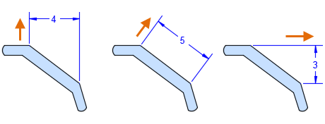
Unidirectional dimensions text are written in horizontal direction.
What is… an Extension line an Extension line gap an Extension line extension a Dimension line a Dimension text a leader What size… Is an Arrowhead
They can be orientated either in a horizontal or vertical (or even aligned) fashion.
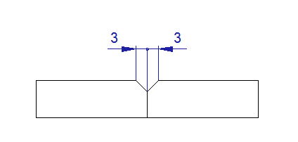
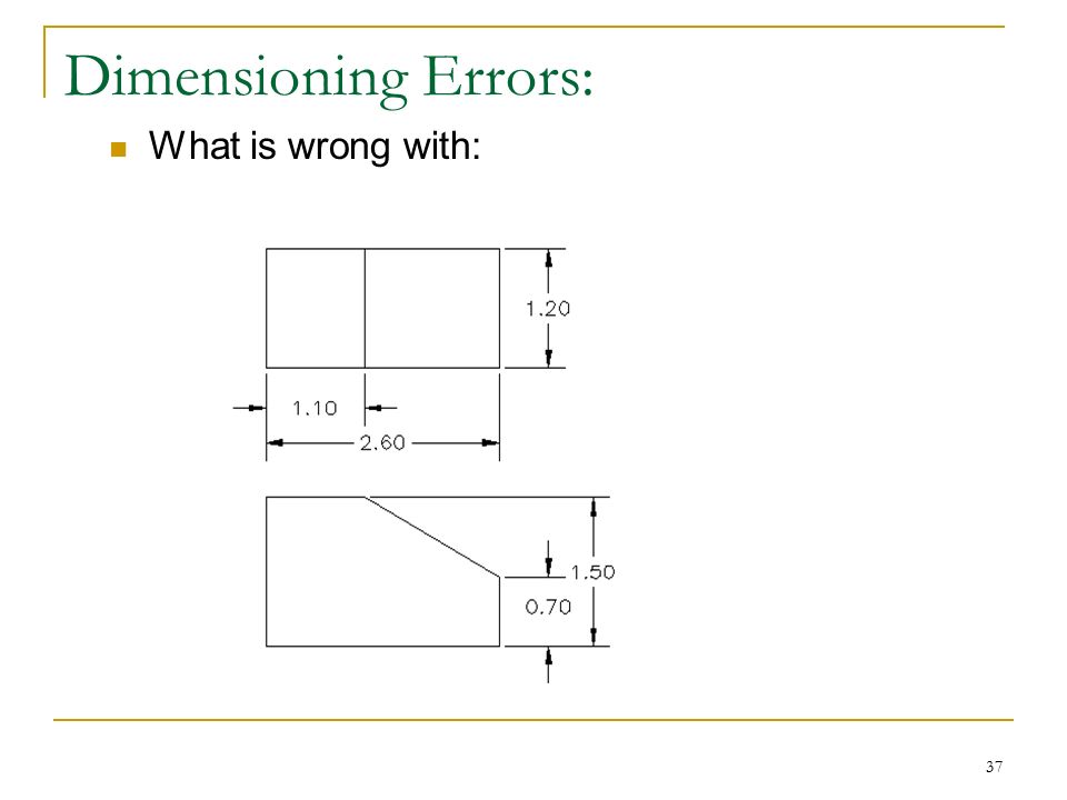
Dimensioning Errors: What is wrong with:
Quiz. Identify the parts, standards and errors shown in the given figure.
Learning Objectives Define the following: Dimension line
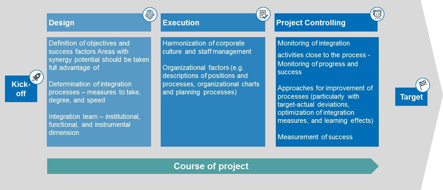
Post Merger Integration ▷ Transaction Advisory
Line Convention. - ppt download

What Is Dimension in Math? Definition, Types, Shapes, Examples
Learning Objectives: Understand the need for dimensioning in
Introduction to Dimensioning - ppt download
Line Convention. - ppt download

Introduction to Dimensioning - ppt download
Instructional Objectives: Bloom's Revised Taxonomy

Introduction to Dimensioning - ppt download
Dimensioning – Basic Blueprint Reading

Dimension and competencies of Responsible Research and Innovation

Line Convention. - ppt download
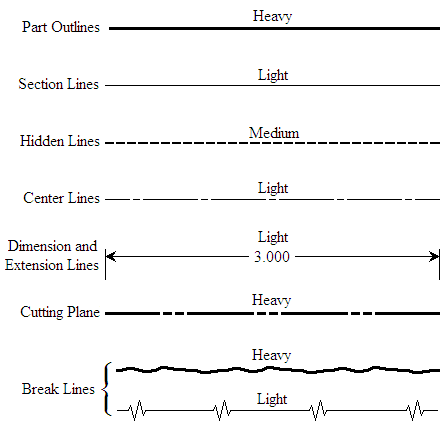
Line Conventions
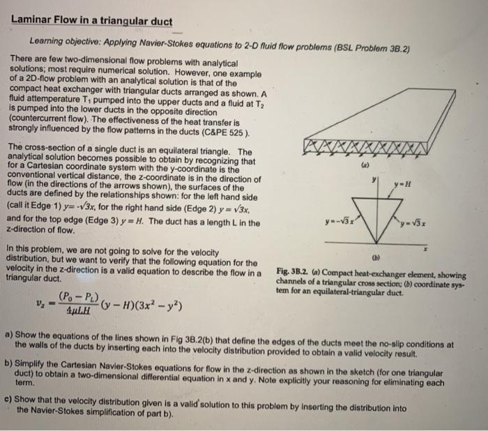
Laminar Flow in a triangular duct Learning objective